by Shubham Kumar
Reference signals are unique signals only present in Physical channels and are used to deliver a reference point for resource scheduling during Uplink and downlink transmission. It occupies specific resource elements within the grid.
NR constitutes of 4 reference signals i.e.
- DMRS(Demodulation Reference Signal)
- PTRS(Phase Tracking Reference Signal)
- CSI-RS(Channel State Information Reference Signal)
- SRS(Sounding Reference Signal)
NR RF VS LTE RF:
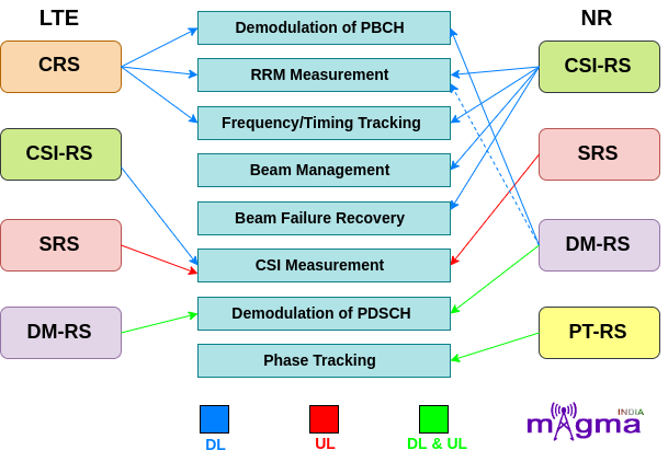
- In LTE, there is a reference signal called C-RS(Cell-specific Reference Signal) which is mainly used for downlink purposes such as demodulation, and channel quality estimation. But in NR, this reference signal is removed and instead, uses different downlink signals for different purposes.
- A new reference signal, PTRS, is introduced which tracks the phase of a local oscillator at the transmitter and receiver end. This is used to counter phase noise at higher frequencies.
- In LTE, DMRS is introduced only in Downlink transmission, but this limitation is no more available in NR. NR introduces DMRS for both downlink and uplink channels.
- In LTE, reference signals are always enabled for maintaining the link between the device and the network but in NR, reference signals are transmitted only when they are required which ultimately optimizes their performance.
Types of Reference Signals:
DMRS
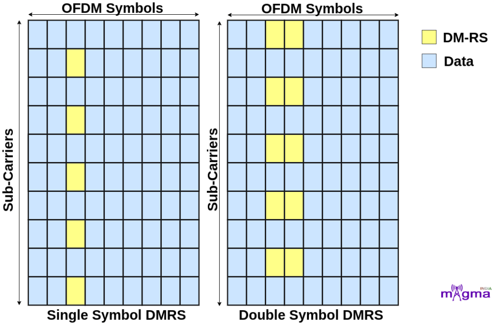
- DMRS(Demodulation Reference Signal) is the reference signal which is used for demodulation i.e. extracting the original signals from the received one(modulated) by altering its frequency and amplitude.
- DMRS is designed specifically for each UE, i.e. no 2 UE’s use the same DMRS for the physical channels demodulation.
- As DMRS is used particularly for demodulation and RRM(Radio Resource Management) measurement, so this is transmitted only when it is needed.
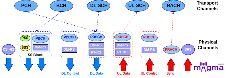
- DMRS is mapped to different physical channels for both Downlink and Uplink. The physical channels that are associated with DMRS are PDSCH, PDCCH PUSCH, and PUCCH.
Apart from this, it is also found in association with PBCH inside the SSB(Synchronization Signal Block). PBCH DMRS occupies 25% of REs(Resource Elements) allocated to PBCH. The REs occupied by the PBCH DMRS are dependent on the PCI(Physical Cell Id) value and its location is determined by the formula ‘PCI mod4’.
- Multiple orthogonal DMRSs i.e. isolated from each other’s effects, can be allocated to support MIMO(Multiple Input and Multiple Output) transmission for higher throughput. It supports up to about 12 orthogonal layers.
- The network controls the rate of transmission of DMRS signals based on rate change. In high mobility scenarios, tracking fast changes in the channel increases the rate of transmission of DMRS signal whereas, in low-speed scenarios where the channel shows little change, it sends this information occasionally.
- DMRS is also found in association with PTRS only once per transmission. DMRS can also be beamformed.
PTRS
- PTRS(Phase Tracking Reference Signal) is used to track the phase of the local oscillator present at the transmission and receiver end.
- The initial angle made by a sinusoidal function of a waveform generated by an oscillator is known as a phase. Any kind of fluctuations that occur in the phase of a waveform is called phase noise. The orthogonality of the subcarriers gets destroyed due to ICI(Inter-Carrier Interference) and this phase noise causes a common phase rotation to all the subcarriers known as CPE(Common Phase Error).
PTRS is responsible for minimizing the effect of the oscillator phase noise on system performance, especially at mmWave frequencies. The phase noise increases with an increase in the frequency of waves.
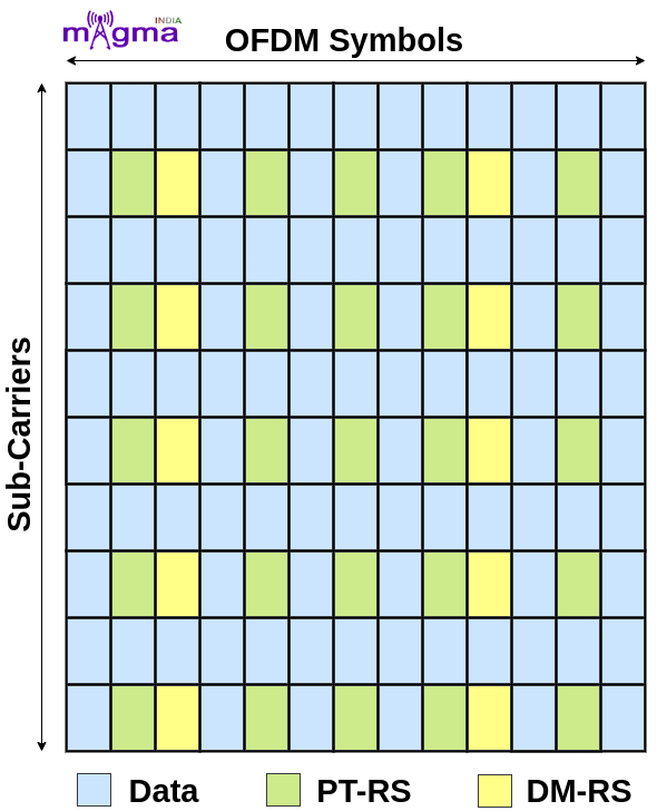
- PTRS has a low density in the frequency domain and high density in the time domain as phase noise tends to change across time but remains the same across the frequency domain. Or in other words, there are low correlation characteristics among the consecutive OFDM symbols.
- PTRS occurs only in combination with DMRS in physical channels. It is present in both uplink and downlink with PUSCH and PDSCH channels respectively.
- PTRS allocation within subcarriers is carried out depending on the quality of the oscillators, carrier frequency, subcarrier spacing, modulation, and coding schemes that are used.
SRS
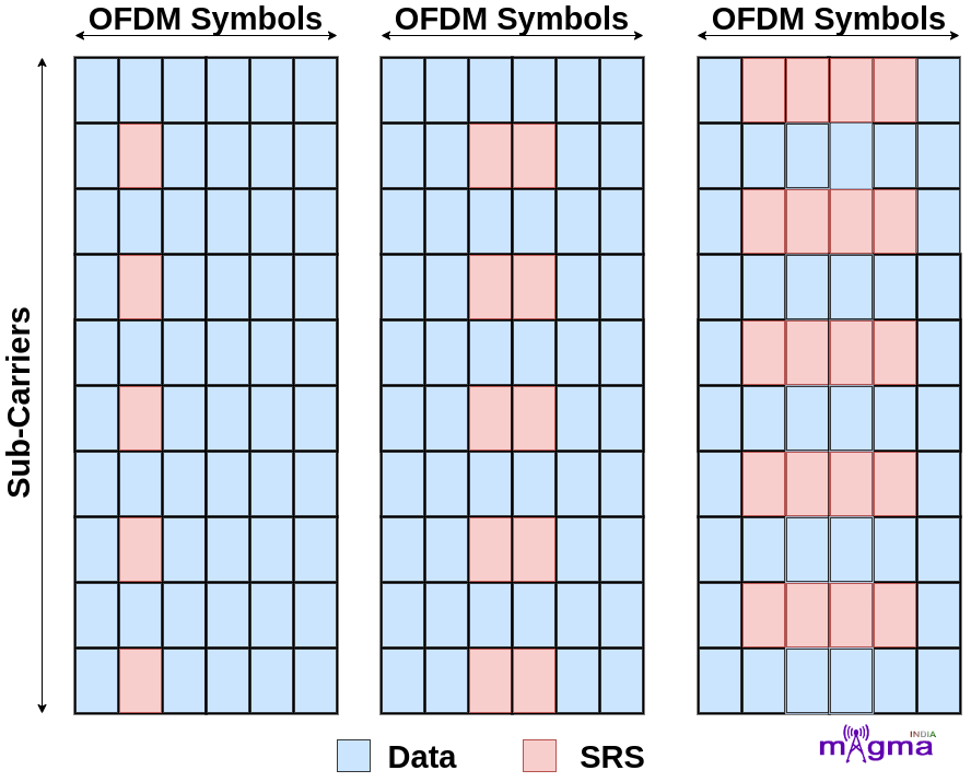
- SRS(Sound Reference Signal) is an uplink reference signal transmitted by UE which is used by the gNodeB to estimate the uplink channel quality over a wider bandwidth.
- Unlike DMRS and PTRS, SRS is not associated with any uplink physical channels but supports uplink resource scheduling and link adaption(selecting an appropriate modulation and coding scheme to maximize the transmission of user bit rate).
- SRS resources span over 1, 2, or 4 consecutive symbols in the time domain. It is always transmitted in the last 6 symbols of the slot.
- SRS provides information about the combined effect of multipath fading, scattering, Doppler, and power loss of the transmitted signal. This information is used by the base station for beam management and power control of the signal.
- Max of 12 UEs can transmit SRS simultaneously using 1 antenna port.
CSI-RS
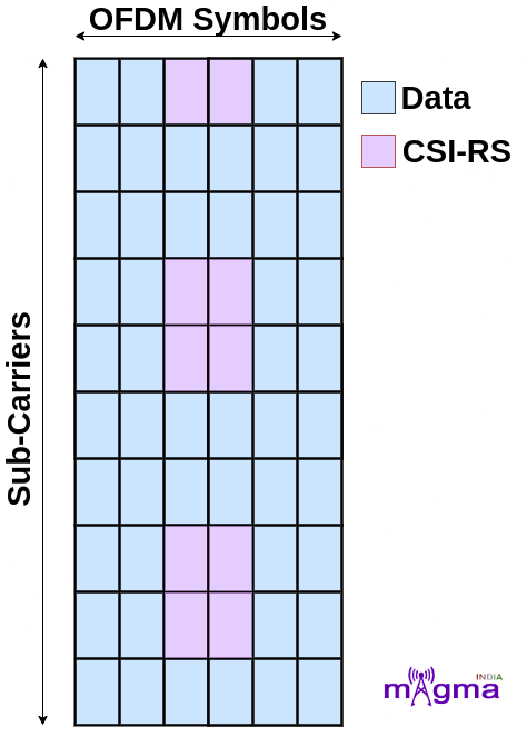
- CSI-RS(Channel State Information Reference Signal) is a downlink reference signal used by UE to measure the quality of the downlink channels and report this to the base station through the CQI(Channel Quality Indicator) report. This information is used by gNodeB to implement appropriate modulation schemes, code rates, beamforming, etc.
- It is used for the calculation of RSRP(Reference Signal Received Power), RSRQ(Reference Signal RecivedQuality), and SINR(Signal Interference + Noise Ratio) during mobility and beam management in connected mode.
- It is also used in frequency and time tracking, and UL reciprocity-based precoding(channel estimation in uplink so that it can be directly used for link adaption in the downlink). For time and frequency tracking, CSI-RS transmission can either be periodic or aperiodic.
- 5GS(5G System) allows a high level of flexibility in CSI-RS configurations, its resources can be configured up to 32 ports.
- CSI-RS resources can be scheduled on any OFDM symbols within the slot but it usually occupies 1, 2, or 4 OFDM symbols based on configured number of ports.
- CSI-RS is uniquely configured for each UE but multiple UEs can share the same resources as they all are served by the same gNB.